
The windings of the DC motor rotate in the DC magnetic field to induce AC potential, which is then converted into DC potential through the commutation device. When the DC motor is working, if the induced potential is overcome by the external DC voltage and the current flows through the winding, the electromagnetic power is input, and after offsetting various losses, it is converted into mechanical power on the motor output shaft to drive the equipment to operate; if the induced potential overcomes To output DC current due to winding voltage drop, power equipment is required to drive the motor shaft to rotate, offset various losses and then convert it into electrical power for output to external circuits. The electromagnetic power at this time includes armature winding resistance loss and electrical power output to external circuits.
The magnetic poles of the DC motor are fixed, the DC current flows through the magnetic pole coils to generate a DC magnetic field, and the armature winding and commutation device rotate synchronously. Since the stationary brush and the commutation device, which are fixed relative to the magnetic pole, are always in sliding contact, a seamless connection between the DC of the external line and the AC within the winding is achieved.
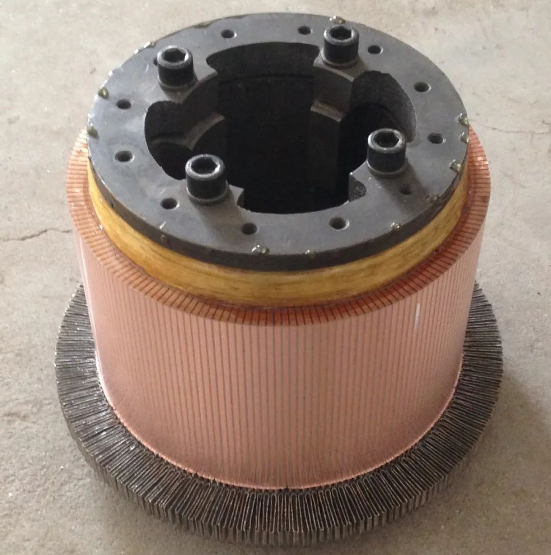
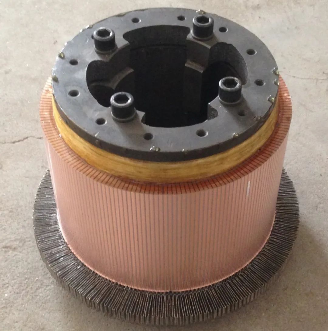
The commutator consists of many commutator segments, which are insulated from each other by mica materials and are also insulated from the ground.

The armature winding of a DC motor is made up of coil components made up of insulated wires, which are embedded in the slot of the motor armature core. These coils are connected to the commutator segments according to certain rules. Coil components may be single- turn or multi-turn. Generally, small-capacity motors have a multi-turn structure, while large-size motors have a single-turn structure. The number of commutator segments is directly related to the number of slots in the motor.
When there is only one element side per slot per layer, the number of commutation pieces is equal to the number of slots. Only when the center of the insulating piece is aligned with the center of the core slot or tooth can a symmetrically terminated winding be achieved. At this time, the brush only needs to be placed on the main On the commutator segment under the polar axis, the maximum potential can be obtained, and the potential of the component short-circuited by the brush is equal to zero or close to zero. When there is more than one component side per slot per layer, it is impossible to align the center of each insulating piece with the core slot, but the center line of the integer pair of commutator segments should be aligned with the center line of the core slot or tooth. If the press installation is not carried out according to the above rules, the brush position should be moved through the same angle accordingly.
In the actual application process, we found that some DC motors have an odd number of commutator segments, and some have an even number. This is directly related to the number of motor slots and winding type. For example, the number of armature slots and winding elements of a single-wave winding motor. The number of pieces and the number of commutation pieces cannot be an even number, but must be an odd number, otherwise the armature cannot be connected to a closed circuit after the wire is embedded. In In order to increase the armature resistance, permanent magnet DC motors generally use single-wave windings, so their number of commutating segments is an odd number instead of an even number.
Online consultation
If you are interested in our products and want to know more details, please leave a message here and we will reply to you as soon as possible.
